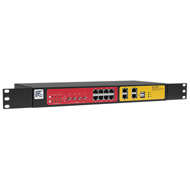
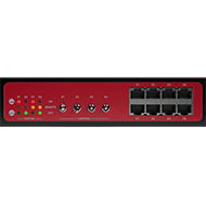
SEC3ER
Relay-controlled 4-Port Ethernet Line Breaker with integrated I/O module
Processor
ARM Cortex-A8 1 GHz
Mass storage
512 MB SLC NAND Flash
Memory
256 MB DDR3L
Ethernet relay interfaces
- 4x RJ45 paired Ethernet interfaces
(Compatible with 10M/100M/1G/10G Ethernet)
- At least 100,000 switching operations at a maximum of two switching operations per second
- Power over Ethernet (PoE) pass-through for classes 0-4 is supportedControl switch
4x 3-way toggle switch for Ethernet interfaces E1-E4
Network interface
2x RJ45 10/100BASE-T
Serial interfaces
2x RJ45 RS232 / RS422 / RS485
Baud Rate: 300 115200 BaudUSB interface
2 x USB 2.0 up to 480 Mbps
Digital input
8x Digital Input
Input voltage: 0 24 V DC (UDI1-8_max: 30 V DC)
Input level low: ≤ 2.96 V DC ± 1%
Input level high: ≥ 3.49 V DC ± 1%
Input impedance: 1.28 MΩ ±2%
Sampling rate: max. 500 Hz ± 5%
Linecross-section: 0.1293.31mm²
(AWG 26...12, solid or stranded wire)Digital output
8x Digital Output (MOSFET P-Channel high side)
Input voltage VSO: 9 24 V DC- UVSO_max: 30 V DC
- I VSO_max: 4 A
- UDO1-8 = VSO - {0.4 V @ 0 A .. 1 V @ 0.5 A}
Max. switching frequency: timpulse ≤ 2 kHz ± 25%
Overcurrent protection - switchover to high-impedance state in the event of a fault:- if 500 mA limit is exceeded
- when switching on load ≥ 350mA
- switch-off time in case of error: 65µs ± 5%
(with 22 Ω and UVSO = 24 V DC) - deactivation switch-off of outputs can be reset by software
Line cross-section: 0.1293.31mm²
(AWG 26...12, solid or stranded wire)ESD
All interfaces are ESD protected
(ESD, surge and burst see EMC)Diagnostics (Status LEDs)
PWR: Power LED
USR: LED freely configurable by software
CPU: LED to show different software conditions
COM1/COM2: Send and receive LED for serial interfaces
ETH0/ETH1: Link and activity LED for Ethernet interfaces
DI 1 8: Status LED for digital input (green if high level)
DO 1 8: Status LED for digital output (green if output active; red if output deactivated due to error)
E1 E4: Three status LEDs each for displaying the current connection status of the Ethernet relay interfaces E1-E4 (red if interface is active; orange if interface is controlled by software; green if interface is inactive)Additional functions
- 4x bistable relays for Ethernet pairs E1-E4
- Battery buffered real time clock (RTC)
- Hardware watchdog
- Temperature monitoringPower supply
- Input Voltage 115 / 230 V AC (85 - 264 V AC)
- Starting current max. 1.5 A
- Input frequency 47 - 63 Hz
- Power consumption max. 65 W
- IEC inlet, snap-in (IEC 60320-C14)Dimensions W/H/D
approx. 354mm/44mm/192mm (without mounting brackets)
Mounting
19" rack mounting with mounting brackets (included in scope of delivery)
IP Code
IP20
Rotating parts
None
Weight
approx. 2 kg
Environmental- / storage temperature
-20° C to 60° C / -40° C to 85° C
Rel. humidity
5 % to 95 % non-condensing
Approval
CE
Standards
EN 61000-6-2: 2019
EN 61000-6-3: 2007 + A1:2011
FCC 47 CFR Part 15 Subpart B
ICES-003, Issue 7 & ICES-Gen, Issue 1Conformity
RoHS, REACH, WEEE, EMC, UKCA, FCC, ICES
Electromagnetic Compatibility (EMC) – Emission Requirements:
EN 55016-2-1: 2014 + A1:2017
Conducted emission on power supply lines in the frequency range 150 kHz - 30 MHz
EN 55016-2-1: 2014 + A1:2017
Conducted emission on telecommunication lines in the frequency range 150 kHz - 30 MHz
EN 55016-2-3: 2017
Electric field radiated emission in the frequency range 30 MHz 1 GHz
EN 55016-2-3: 2017
Radiated emission from the enclosure in the frequency range above 1 GHz
EN 61000-3-3: 2013
Voltage fluctuations and flicker impressed on the public low-voltage system with rated current ≤ 16 A per phase
EN 61000-3-2: 2014
Harmonic current emissions impressed on the public low-voltage system with rated current ≤ 16 A per phaseElectromagnetic Compatibility (EMC) – Immunity Requirements:
EN 61000-4-2: 2009
Immunity to electrostatic discharge (ESD)
- Contact discharge ± 4 kV
- Air discharge ± 8 kV
EN 61000-4-3: 2006 + A1:2008 + A2:2010
Immunity to RF electromagnetic fields
- 80 1000 MHz, test level 10 V/m
- 1.4 6 GHz, test level 3 V/m
EN 61000-4-4: 2012
Immunity to fast transients (Burst)
- AC power port ± 2 kV
- Signal lines ± 1 kV
EN 61000-4-5: 2014 + A1:2017
Immunity to surges on power supply lines (Surge)
- AC power port: line <-> ground ± 2 kV
- AC power port: line <-> line ± 1 kV
EN 61000-4-5: 2014 + A1:2017
Immunity to surges on shielded signal lines (Surge)
- Shielded lines ± 1 kV
EN 61000-4-6: 2014
Immunity to conducted interference induced by radio-frequency fields
- 150 kHz 80 MHz, test level 10 V
EN 61000-4-8: 2010
Immunity to power frequency magnetic field
magnetic field strength 30 A/m frequency 50 + 60 Hz
EN 61000-4-11: 2004
Immunity to voltage dips and interruptions
- residual voltage 0% / 1 cycle
- residual voltage 40% / 10 cycle
- residual voltage 70% / 25 cycle
- residual voltage 0% / 250 cycleElectromagnetic Compatibility (EMC)
- FCC 47 CFR Part 15 Subpart B
- ICES-003, Issue 7 & ICES-Gen, Issue 1
ANSI C63.4:2014 + ANSI C63.4a:2017
AC powerline conducted emission
ANSI C63.4:2014 + ANSI C63.4a:2017
Electric field radiated emission in the frequency range 30 1000 MHz
ANSI C63.4:2014 + ANSI C63.4a:2017
Electric field radiated emission in the frequency range 1 6 GHz